A drawing shows a narrow opening in a PCB. The purchasing description says “slot drill”, while the existing machine program uses a routing cycle. Before ordering a replacement, resolve that difference. A feature name describes the opening you want; it does not fully describe the tool or the way the machine will produce it.
For a PCB slot, send the width, overall length, board construction and intended machine cycle. For a routed profile, include the contour and edge requirements. The cutter then needs to be checked against that operation.
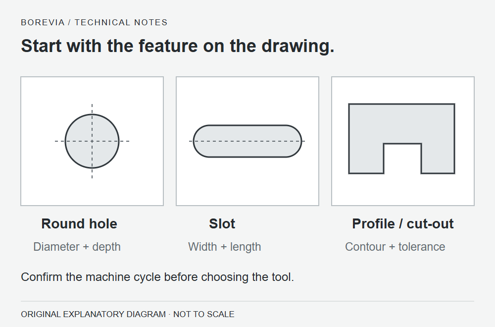
A slot on the drawing is only the starting point
Drilling can produce an elongated opening through a defined sequence of overlapping holes. Routing produces a contour through controlled cutter movement. Which method is appropriate depends on the feature, equipment and process. Do not take a normal round-hole drill and assume it can accept the sideways cutting load of a router.
Slot-drilling instructions are tool-specific. An operating sequence published for another manufacturer’s slot drill is not a setting sheet for the tools in our catalogue. Ask the process owner to confirm the cycle and the supplier to confirm tool compatibility.
What changes in the enquiry?
| Check | Slot-drill enquiry | Router-bit enquiry |
|---|---|---|
| Feature | Slot width, end-to-end length and end shape. | Profile or cut-out drawing, including internal corners. |
| Operation | Slot-drilling cycle and current tool reference. | Routing path, entry method and current cutter reference. |
| Working length | Board stack and required flute length. | Board thickness, cutting depth and working length. |
| Inspection | Slot dimensions, end shape and edge condition. | Contour accuracy, edge condition and any corner requirement. |
| Setup | Machine, holder, support and extraction. | Machine, holder, panel support and extraction. |
Write down what “slot length” means
A slot dimension may refer to the complete opening or to the distance between its rounded-end centres. Those are different dimensions. Include a sketch or drawing with dimension arrows rather than sending two unexplained numbers.
Also identify whether the requirement applies before or after plating. A finished feature dimension is not automatically the required cutting diameter. Any process allowance should come from the board manufacturing process, not an estimate added to the purchase order.
Use the catalogue range carefully
Our PCB slot-drill family lists cutting diameters of 0.40–3.00 mm. The selected catalogue groups show flute lengths of 5.5 mm for 0.40–0.50 mm diameters, 6.7 mm for 0.55–0.65 mm, and 8.7 mm for 0.70–3.00 mm. These are listed combinations, not permission to choose any diameter with any length.
The PCB router-bit page takes an application-led approach: send the required dimensions, material and profile details for confirmation. Do not carry the slot-drill range across to the routing family. Current availability and the exact tool specification are confirmed at quotation.
Compare a trial against the drawing
Before a trial, agree how the slot or profile will be measured and what edge condition is acceptable. Retain the tool reference, board stack, machine program revision and inspection photographs. If the tool and cycle both change, record both changes; the result alone will not tell you which one made the difference.
For an existing defect, start with the hole-quality inspection checklist. For a new purchase, use the tooling RFQ checklist to keep the quotation tied to a clear specification.
Send the slot or profile details through our enquiry form. Include the current tool and operation where known; “not yet confirmed” is more useful than guessing a cutter type.
Process reference: UNION TOOL SX24 slot-drilling guidance. Its sequence and settings apply to the stated tool series, not to BOREVIA catalogue tools.
Discuss your application
Share the board material, tool dimensions and the issue you are seeing.
Prepare an enquiry ↗